j

Lorem ipsum dolor amet, consect adipiscing elit, diam nonummy.

Follow Us

Search

P&ID Tool

Simplifying Well Control P&IDs

Summary

Context

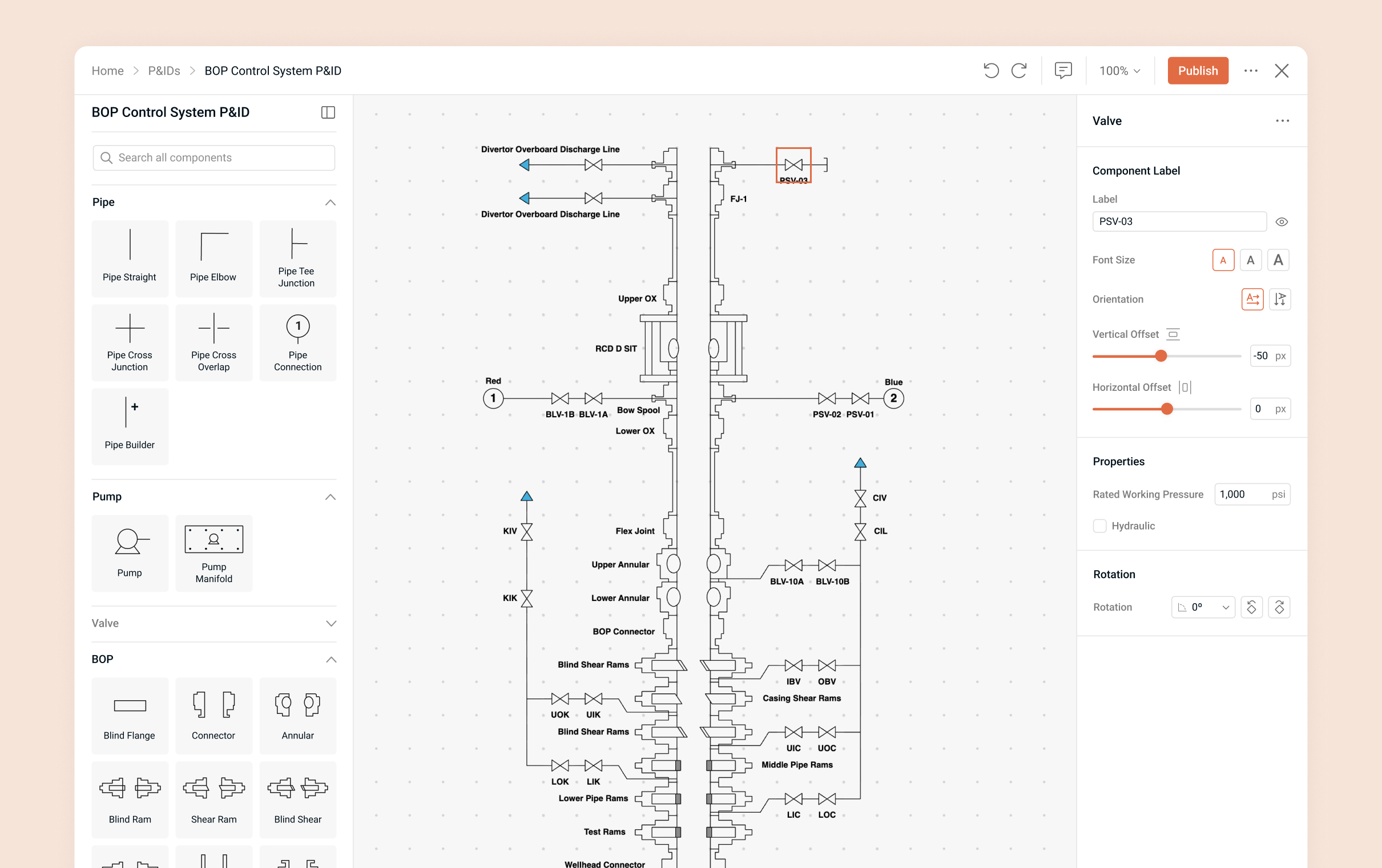
Well control is critical to safe drilling operations. Many oil and gas professionals rely on P&ID diagrams (Piping & Instrumentation Diagrams) to visualize, validate, and communicate equipment layouts and associate flow paths. Traditional tools for creating P&IDs are either too generic or overly complex, making it difficult to build accurate diagrams.

I led the design of a well control P&ID builder tool that simplifies diagram creation, ensures accuracy, and integrates with operational workflows.

My Role

  • Led the end-to-end UI/UX design
  • Designed P&ID icons and application screens
  • Built and delivered design system components and the final UI
  • Worked closely with subject matter experts and developers to ensure accuracy and feasibility
  • Conducted usability testing, gathered feedback, and refined the design accordingly

The Problem

  • Generic diagramming tools lacked BOP- and wellhead-specific elements
  • Engineers had to manually adapt symbols or create custom components, slowing down workflows.
  • Errors in diagrams had high-stakes consequences, without built-in validation, mistakes risked compromising safety and compliance

Engineers spent significant time wrestling with tools rather than focusing on accurate, safe well control design.

Existing schematics used

Discovery

Analyzing Components

I reviewed numerous well control diagrams and components to understand which elements were essential and how they should be represented and connected. I collaborated closely with subject matter experts to validate the components and their visual depiction.

Various diagrams of well control components

Learning from Existing Tools

I researched different P&ID styles and tool functionalities to understand levels of detail, labeling practices, and established visual conventions. From this, I defined the style direction and outlined the tool’s key requirements: a drag-and-drop component library, smart connections, customizable labeling, and built-in compliance checks.

P&ID schematics and tools for different industries and applications

Design

Creating a Component Library

I designed a library of well control specific components and standard components required for P&ID schematics with consistent styling across the elements. I ensured each element was visually clear, and aligned with industry standards through collaboration with subject matter experts.

Guiding Users with a Smart Diagram Builder

The editor was designed around simple drag-and-drop placement with smart connections that automatically linked components. It emphasized the core functionalities engineers needed, avoiding unnecessary styling options since the focus was on modeling and validating equipment structures and their functional relationships. Features such as grid snapping, automated connections, and enforced valid connections with error messages that pointed users to issues made it easier to build accurate diagrams quickly.

Adding Context to Diagrams

Users could rotate components, add pressure limits, and apply labels. Labels featured simple styling options for adjusting the size and position to ensure they remained legible within the diagram. Clear labeling was essential so viewers could easily identify which label corresponded to each component. In addition to labels, users could access an annotation mode and place annotations anywhere on the diagram to provide further context.

Design System & Developer Handoff

I built a UI design system in Figma with components, interaction states, and annotations. Screens also included annotations explaining functionality, providing developers guidance for implementation.

Examples of interaction states for components with developer notes

Improving Through Feedback

The product went through user acceptance testing with 40 participants who rebuilt an existing schematic using the tool. They provided feedback on the editor during the task, which I applied to refine the final designs above.

UAT Exercise
Examples of user feedback from UAT

Outcome

Designing this tool reinforced the importance and value of domain-specific tools, especially in safety-critical industries. By working closely with subject matter experts, I created a tool that saves time, improves accuracy, and contributes to safer operations.